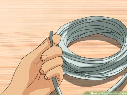
 Unroll the required length of network cable and add a little extra wire, just in case. If a boot is to be fitted, do so before stripping away the sleeve and ensure the boot faces the correct way.
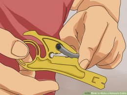
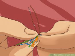
Carefully remove the outer jacket of the cable. Be careful when stripping the jacket as to not nick or cut the internal wiring. One good way to do this is to cut lengthwise with snips or a knife along the side of the cable, away from yourself, about an inch toward the open end. This reduces the risk of nicking the wires' insulation. Locate the string inside with the wires, or if no string is found, use the wires themselves to unzip the sheath of the cable by holding the sheath in one hand and pulling sideways with the string or wire. Cut away the unzipped sheath and cut the twisted pairs about 1 1/4" (30 mm). You will notice 8 wires twisted in 4 pairs. Each pair will have one wire of a certain color and another wire that is white with a colored stripe matching its partner (this wire is called a tracer).
Inspect the newly revealed wires for any cuts or scrapes that expose the copper wire inside. If you have breached the protective sheath of any wire, you will need to cut the entire segment of wires off and start over at step one. Exposed copper wire will lead to cross-talk, poor performance or no connectivity at all. It is important that the jacket for all network cables remains intact.
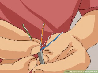
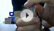
 Untwist the pairs so they will lay flat between your fingers. The white piece of thread can be cut off even with the jacket and disposed (see Warnings). For easier handling, cut the wires so that they are 3/4" (19 mm) long from the base of the jacket and even in length.
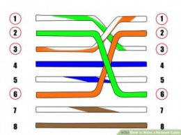
 For our demonstration in the following steps, we will use 568B, but the instructions can easily be adapted to 568A.
568B - Put the wires in the following order, from left to right:
white orange
orange
white green
blue
white blue
green
white brown
brown
568A - from left to right:
white/green
green
white/orange
blue
white/blue
orange
white/brown
brown
For our demonstration in the following steps, we will use 568B, but the instructions can easily be adapted to 568A.
568B - Put the wires in the following order, from left to right:
white orange
orange
white green
blue
white blue
green
white brown
brown
568A - from left to right:
white/green
green
white/orange
blue
white/blue
orange
white/brown
brown
You can also use the mnemonic 1-2-3-6/3-6-1-2 to remember which wires are switched.
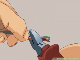
Press all the wires flat and parallel between your thumb and forefinger. Verify the colors have remained in the correct order. Cut the top of the wires even with one another so that they are 1/2" (12.5 mm) long from the base of the jacket, as the jacket needs to go into the 8P8C connector by about 1/8", meaning that you only have a 1/2" of room for the individual cables. Leaving more than 1/2" untwisted can jeopardize connectivity and quality. Ensure that the cut leaves the wires even and clean; failure to do so may cause the wire not to make contact inside the jack and could lead to wrongly guided cores inside the plug.
Keep the wires flat and in order as you push them into the RJ-45 plug with the flat surface of the plug on top. The white/orange wire should be on the left if you're looking down at the jack. You can tell if all the wires made it into the jack and maintain their positions by looking head-on at the plug. You should be able to see a wire located in each hole, as seen at the bottom right. You may have to use a little effort to push the pairs firmly into the plug.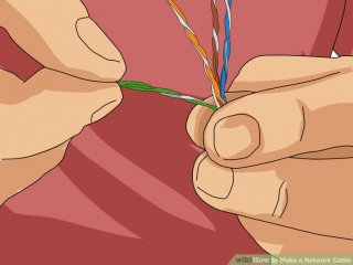 The cabling jacket should also enter the rear of the jack about 1/4" (6 mm) to help secure the cable once the plug is crimped. You may need to stretch the sleeve to the proper length. Verify that the sequence is still correct before crimping.
Place the wired plug into the crimping tool. Give the handle a firm squeeze. You should hear a ratcheting noise as you continue. Once you have completed the crimp, the handle will reset to the open position. To ensure all pins are set, some prefer to double-crimp by repeating this step.
10
Repeat all of the above steps with the other end of the cable. The way you wire the other end (568A or 568B) will depend on whether you're making a straight-through, rollover, or cross-over cable (see Tips).
11
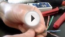
Test the cable to ensure that it will function in the field. Mis-wired and incomplete network cables could lead to headaches down the road. In addition, with power-over-Ethernet (PoE) making its way into the marketplace, crossed wire pairs could lead to physical damage of computers or phone system equipment, making it even more crucial that the pairs are in the correct order. A simple cable tester can quickly verify that information for you. Should you not have a network cable tester on hand, simply test connectivity pin to pin.

YOU MIGHT ALSO LIKE

Share this Post
latest post
-
 Split Ethernet cable into two February 10, 2019
 -
 What is Ethernet Patch Cables? February 5, 2019
 -
 Military Fiber Optic cable January 31, 2019
 -
 Networking cable types January 26, 2019
 -
 Fluke Ethernet cable Tester January 21, 2019
 -
 Molex Fiber Optic cable January 16, 2019
 -
 Buy Ethernet Cables online January 11, 2019
 -
 Harford County cable Network January 6, 2019
 -
 Serial to Ethernet cable January 1, 2019