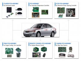
 Market trends driving electronics manufacturers to include FE analysis and strain testing of PCBA’s As machinery becomes increasingly sophisticated the reliance on electronic controls is growing. The building block of any electronic control system is the PCBA and these can be found everywhere; in home appliances, automobiles, wind turbines, data centers and personal computers. Although taken for granted, the orderly functioning of our every day life is deeply dependent on the reliable operation of these electronic controls and PCBA’s. Examples of PCBA’s Used in Automotive Assuring this reliable operation has become more challenging due to the RoHS lead free solder requirements imposed by the European Union as well as a shift away from traditional flat pack surface mount intergrated circuits toward a ball grid array (BGA) package style. The BGA packaging offers a higher pin density with a pitch of less than 1mm. The trade off is a less mechanically robust connection between the BGA and circuit board. In response to these challenges electronics manufactures are increasingly including FE analysis in their design process and strain gage testing as part of their manufacurability and reliability assessment. In the September issue of SMT magazine an article titled “A Case Study on Evaluating Manual and Automated Heat Sink Assembly using FEA and Testing” outlines an approach to characterizing and reducing the stresses incurred by a PCBA during the manufacturing process. Traditional Strain Gage Techniques – Minimal Data with Maximum Wiring
This approach to measuring strain of PCBA’s is defined by standard IPC/JEDEG 9704A January 2012, titled “Printed Circuit Assembly Strain Gage Test Guideline”. The standard outlines how a PCBA can be instrumented with both rosette style and in line strain gages. Each individual strain gage provides a single strain measurement representive of the average strain within the area covered by the strain gage. Each strain gage also requires dedicated copper wiring to conduct a low voltage electrical signal back to the data acquisition system. A rosette strain gage requires six copper wires while an inline strain gage two copper wires. Great care needs to be taken in routing the harness so as not to cause interference with the mechanical flexing of the PCBA under test. The image to the right shows a PCBA instrumented with two rosette strain gages, each requiring six copper wires. In summary, the technique of using ‘point sensor’ strain gages is severely limiting and also requires some prior knowledge of where the critical locations might be.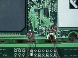 The entire point of a test program is that the location of critical points for stress and/or temperature are not always known. A Better Way – High Definition Fiber Optic Sensing (HD-FOS) from Luna Innovations Fortunately Luna Innovations ODiSI platform using HD-FOS technology offers manufactures a method of strain and temperature testing that is ideally suited for testing PCBA’s. Luna’s ODiSI, with HD-FOS, uses a standard un-altered fiber optic cable to create a virtually continuous line of strain or temperature sensors. Fiber optic cable is only 150 microns in diameter and can be bonded to the PCBA simply and unobtrusively either in a straight line, a grid pattern, or a pattern replicating a rosette style strain gage. A strain or temperature measurement is taken every 0.64 mm along the length of fiber offering a high density picture of strain that is perfect for determing the location of critical stress points. A fiber sensor one meter in length offers over 1000 data points. The fiber is dielectric and can be routed without separate insulation; because of its immunity to EMI/EMC, no special filtering will be required to prevent interference from any high frequency switching. Further more these strain meausurements are routed back to acquistion device through a single fiber thus greatly simplifying instrumenting the device under test. . Luna’s HDFOS – Using Fiber to Measure PCBA Component and Trace Temperature High definition fiber optic sensing can also be used to sense temperature with all of the same advantages highlighted for strain sensing; a measurement can be made every 0.64 mm which is perfect for identifying hot spots; the fiber is a dielectric and immune to EMI which can avoid the need for separate insulation, shielding and filtering; the data connection to the signal processing unit from the fiber sensor is through the same fiber sensor and this greatly simplifies the harness; the small diameter of the fiber sensor allows measurements of locations unaccessible to strain gages or thermocouples. For high volume applications such as automotive, even very small problems, can be very big problems This simple well understood fact underlines why the design and manufacturing process for PCBA’s is so standardized and why the testing process is formal and rigorous. A small problem in the design or manufacturer of a PCBA, undetected in the design and test phase, can be the source of enormous cost, loss of customers and brand reputation. These effects are multiplied when volumes are high and supply chains are filled with defective product. Strain gages and thermocouples are technologies from the early 20th century and 19th century respectively. High definition fiber optic sensing represents 21st century design validation technology for manufactures building 21st century designs and serving 21st century customers.
YOU MIGHT ALSO LIKE

Share this Post
latest post
-
 Split Ethernet cable into two February 10, 2019
 -
 What is Ethernet Patch Cables? February 5, 2019
 -
 Military Fiber Optic cable January 31, 2019
 -
 Networking cable types January 26, 2019
 -
 Fluke Ethernet cable Tester January 21, 2019
 -
 Molex Fiber Optic cable January 16, 2019
 -
 Buy Ethernet Cables online January 11, 2019
 -
 Harford County cable Network January 6, 2019
 -
 Serial to Ethernet cable January 1, 2019