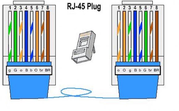
 The following CAT5 wiring diagram and crossover cable diagram will teach an installer how to correctly assemble a CAT-5 cable RJ45 connectors for regular network cables as well as crossover cables. The first set of instructions are for standard network patch cables (EIA/TIA-568B). EIA/TIA-568B, also known as standard Ethernet, is the type of CAT-5 connection used to connect IP security cameras and network video recorders (NVRs) in IP surveillance systems. If you are creating a crossover cable, please click here for the .
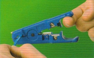
- Using an cat5 cutter and crimping tool, strip about 1/3"of the out jacket of the cat-5 cable. Be sure not to strip or damage any of the pairs of inner cables.
- Assemble the pairs of wires in the following order for network cables (EAI standard / TIA-568B).
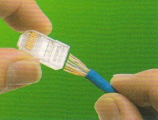
- Insert the wires into the RJ45 jack as seen below. Be sure to keep the wires in the correct order.
- Insert the RJ45 connector into the crimping tool (again carefully make sure the wires stay inserted in the correct order). Crimp down firmly on the crimping tool to permanently attach the RJ45 to the CAT5 cable.
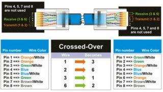
To create a crossover cable with cat-5 cable follow the same instructions as above for except when you get to step #2, use the below crossover cable diagram:
Author
This article is maintained by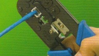
YOU MIGHT ALSO LIKE
How to make a Cat5e Network/Ethernet Cable
How to Make an Ethernet CAT5 RJ45 Crossover Cable

Build Your Own Crossover Cable, USB to Ethernet Extender ...
Share this Post
latest post
-
 Split Ethernet cable into two February 10, 2019
 -
 What is Ethernet Patch Cables? February 5, 2019
 -
 Military Fiber Optic cable January 31, 2019
 -
 Networking cable types January 26, 2019
 -
 Fluke Ethernet cable Tester January 21, 2019
 -
 Molex Fiber Optic cable January 16, 2019
 -
 Buy Ethernet Cables online January 11, 2019
 -
 Harford County cable Network January 6, 2019
 -
 Serial to Ethernet cable January 1, 2019