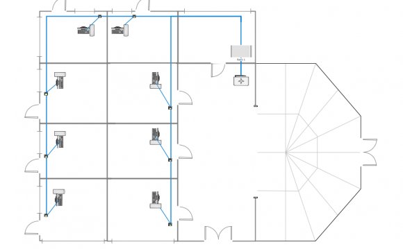
 A network wiring diagram is simply a visual representation of the connection layout of a system or circuit. When terminating twisted-pair copper network cable (CAT cables) to 8-position RJ45 jacks and connectors, T568A and T568B wiring schemes define the order of connections (also known as pinout). If a cable is terminated in a random order of colors on each end, it will not function regularly, if at all.
If you are asking yourself “Do I need a network wiring diagram?”, you should take a look at T568A and T568B wiring schemes to assure your connections are in the right order to assure the cable will function properly.
An important fact to know about the two schemes is that they should not be combined. In other words, the two ends of the cables should terminate with the same scheme (same order of colors). Scheme T568B is more commonly used, but any one of the two schemes would do if you are building a new network. If you are working on an existing network, troubleshooting or expanding the network, it is important to continue using the scheme that is in place. When multiple schemes are used – data signals will not transfer.
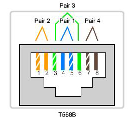
T568A and T568B wiring schemes are TIA/EIA standards which define the pinout (order of connections) for wires in 8-position RJ45 jacks and connectors. The two differ in pairs 2 and 3 (orange and green), which are swapped.
In order to determine which scheme should be used, consider the following information:
- While T568B is the preferred scheme for new networks in the United States, you may choose any one of the two schemes, unless:
- In a case where there is a network in place that needs updating or expanding, use the scheme in place. Do not introduce a new scheme.
- If there are project specifications, use the wiring scheme specified.
There are rare cases where T568A-wired components need to be connected to T568B-wired components In these cases, a crossover cable (a patch cord that has an A-configured plug at one end, and a B-configured plug at the other) will be used to smoothly transition between standards without compromising data.
YOU MIGHT ALSO LIKE


Share this Post
latest post
-
 Split Ethernet cable into two February 10, 2019
 -
 What is Ethernet Patch Cables? February 5, 2019
 -
 Military Fiber Optic cable January 31, 2019
 -
 Networking cable types January 26, 2019
 -
 Fluke Ethernet cable Tester January 21, 2019
 -
 Molex Fiber Optic cable January 16, 2019
 -
 Buy Ethernet Cables online January 11, 2019
 -
 Harford County cable Network January 6, 2019
 -
 Serial to Ethernet cable January 1, 2019